Embedded Programming
Individual Assignment
1) Read the datasheet for the microcontroller you are programming.
2) Program the board you have made to do something, with as many different programming languages and programming environments as possible.
Group Assignment
Compare the performance
and development workflows for different micro controller families.
ATTiny44
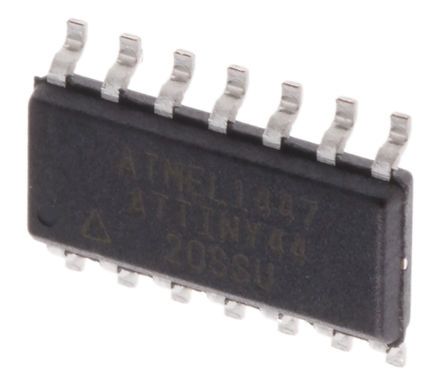
The high-performance Microchip picoPower® 8-bit AVR® RISC-based microcontroller combines 4 KB ISP Flash memory, 256B EEPROM, 256B SRAM, 12 general purpose I/O lines, 32 general purpose working registers,
an 8-bit timer/counter with two PWM channels, a 16-bit timer/counter with two PWM channels,
internal and external interrupts, an 8-channel 10-bit A/D converter, programmable gain stage
(1x, 20x) for 12 differential ADC channel pairs, programmable watchdog timer with internal
oscillator, internally calibrated oscillator, and four software selectable power saving modes.
The device operates between 1.8-5.5 volts.
By executing powerful
instructions in a single clock cycle, the device achieves throughputs approaching one MIPS per MHz, balancing power
consumption and processing speed.
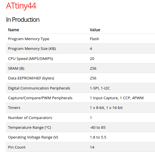
To know more about ATtiny44 just go through the datasheet
These are some basic details about the chip.
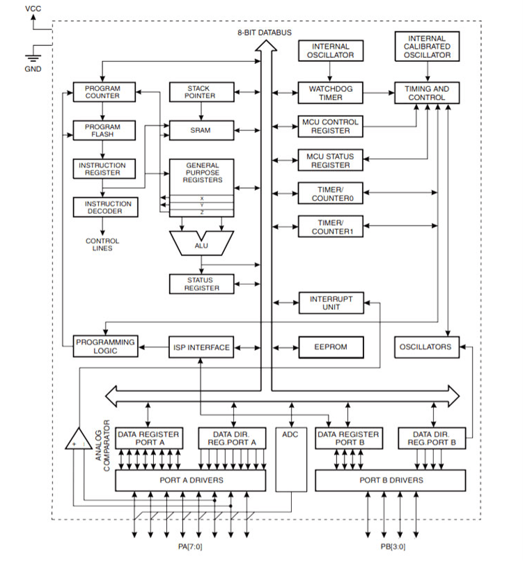
Block Diagram
ATtiny PINS
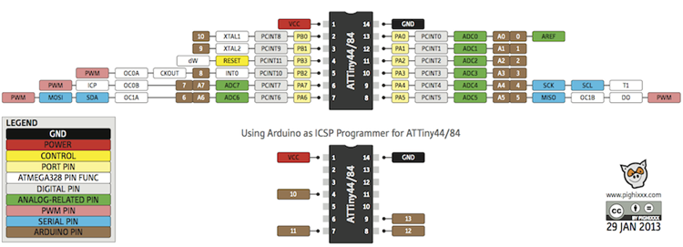
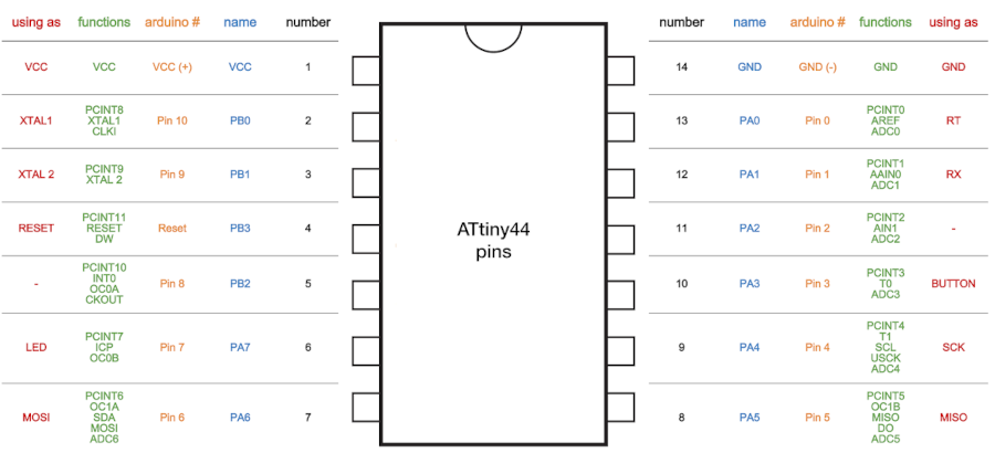
VCC : Supply voltage
GND : Ground
Port B (PB3...PB0) : Port B is a 4-bit bi-directional I/O port with internal pull-up resistors (selected for each bit).
As inputs, Port B pins that are externally pulled low will source current
if the pull-up resistors are activated.so we don't need to add a pull-up resistor externaly for button's and other purpose.
RESET : Reset input. A low level on this pin for longer than the minimum pulse length will generate a reset, even if the clock is not running.a reset will just reset the programm that currently runnig .
Port A (PA7...PA0) : Port A is a 8-bit bi-directional I/O port with internal pull-up resistors (selected for each bit). As inputs, Port A pins that are
externally pulled low will source current if the pull-up resistors are activated.
SCK(Serial Clock) : Programming clock, generated by the In-System
Programmer (Master).
MOSI (Master Out - Slave In) : Communication line
from In-System Programmer (Master) to target AVR being programmed (Slave).
MISO (Master In - Slave Out)
: Communication line from target AVR (Slave) to In- System Programmer (Master).
Hello Echo Board
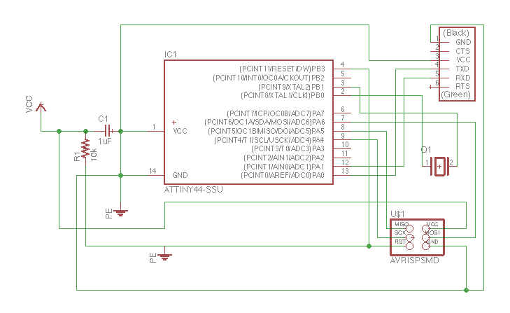
This week we
need to progarmme the Hello-echo board that i designed in the Electronics Design week.
Echo board is
based on the Microchip ATtiny44 . It's a 8-bit RISC based microcontroller. The
Original Design have only the UART Port and I added a Programmable Button connected to pin PA7 with a
Pull-down Resistor and LED connected to PA5
also it's have 20hz External Resonator.
Programming using Arduino IDE
The Arduino software or IDE (Integrated Development Environment) contains a text editor that is generally used for writing, compiling and uploading code in Arduino hardware. It helps to connect and communicate with the Arduino hardware. Arduino IDE can be run on all major operating system platforms like Linux,
Windows, and Mac OS. It is available for both 32-bit and 64-bit OS platforms.
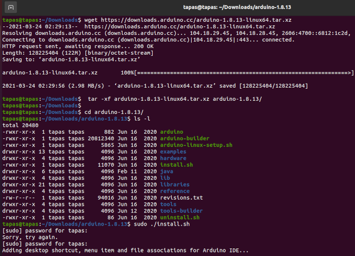
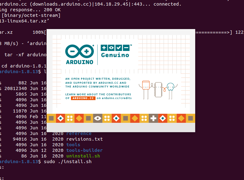
Download the arudino ide download
How to Install Arduino IDE on Ubuntu
Since the original Arduino software does not support the ATtiny44. I have to add some Board directorys for adding my ATtiny44 board to my arduino
enviournment
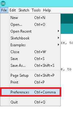
- Go to preference by clicking
File >> Preference
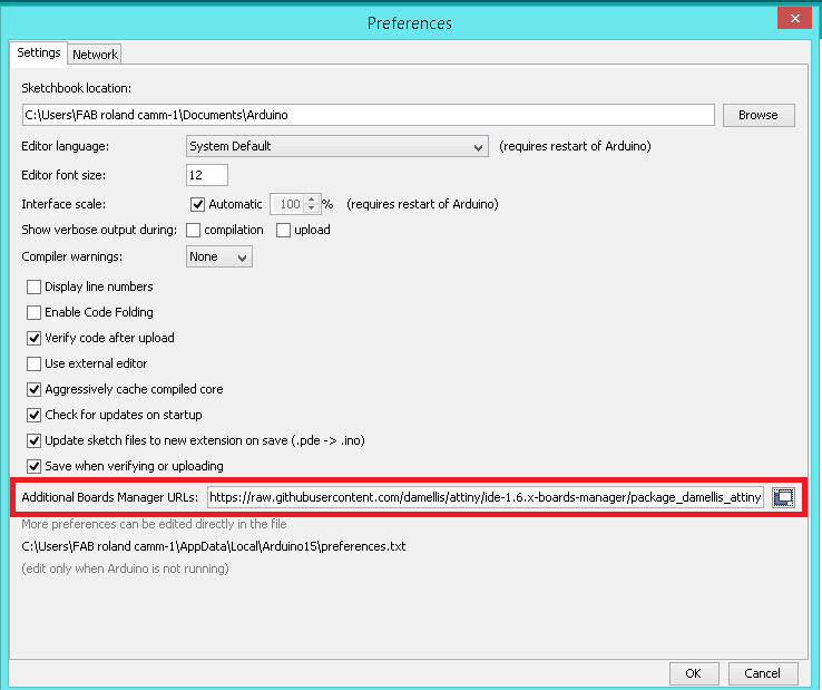
URL to add to the ‘Additional Boards Manager URLs’ field:
https://raw.githubusercontent.com/damellis/attiny/ide-1.6.x-boards-manager/package_damellis_attiny_index.json
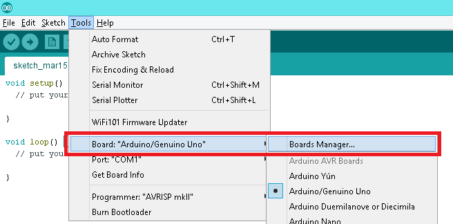
- After adding the URL open Board Manager by clicking
Tools >> Board >> Board Manager
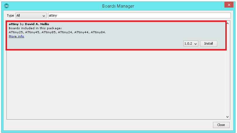
-Search for ATtiny44 in the following Window.(Make sure you have Internet connection).and Install the latest version .
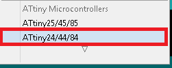
- Now you can select ATtiny44 under the ATtiny Microcontrollers in board Selection
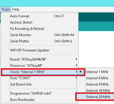
- Select the Clock as 20MHz.
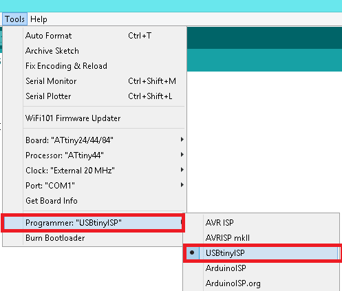
- We are using Fab ISP to programme the Hello-Echo board, so Select the Programmer as USBtinyISP.
Blinking LED
void setup() {
#define LED 8
#define SW 7

void setup()
     {
  pinMode(LED, OUTPUT);
  pinMode(SW, INPUT);
       }

  void loop()
      {
    digitalWrite(LED, HIGH);
    delay(1000);
    digitalWrite(LED, LOW);
    delay(1000);
    }
Toggle led
#define LED PA2
#define SW  PA6

// toggle the led status upon button press

boolean prev_btn_stat=HIGH;
boolean prev_led_stat=LOW;
boolean current_btn_stat;


void setup() {
  // put your setup code here, to run once:
pinMode(LED,OUTPUT);
digitalWrite(LED,LOW);
pinMode(SW,INPUT_PULLUP);
}

void loop()
{
  prev_btn_stat = current_btn_stat;
  current_btn_stat = digitalRead(SW);
  if(!current_btn_stat && (current_btn_stat != prev_btn_stat) )
  {
    delay(5);   //debouncing with 1ms delay
    if ( prev_led_stat )
    {
     digitalWrite(LED,LOW);
     prev_led_stat = LOW;
    }
    else
    {
     digitalWrite(LED,HIGH);
     prev_led_stat = HIGH;
    }
  }

   //delay(200);
}
LED PULL UP
const int ledPin =  7;

int BUTTONState = 0;

void setup()
{
  pinMode(PA2, OUTPUT);
  pinMode(PB2, INPUT_PULLUP);
}

void loop()
{
  BUTTONState = digitalRead(PB1);
  if (BUTTONState == 0
  )
  {
    digitalWrite(PA2, LOW);
  }
  else
  {
    digitalWrite(PA2, HIGH);
  }
}
Click to download the file :
ATTiny44
GND : Ground
Port B (PB3...PB0) : Port B is a 4-bit bi-directional I/O port with internal pull-up resistors (selected for each bit). As inputs, Port B pins that are externally pulled low will source current if the pull-up resistors are activated.so we don't need to add a pull-up resistor externaly for button's and other purpose.
RESET : Reset input. A low level on this pin for longer than the minimum pulse length will generate a reset, even if the clock is not running.a reset will just reset the programm that currently runnig .
Port A (PA7...PA0) : Port A is a 8-bit bi-directional I/O port with internal pull-up resistors (selected for each bit). As inputs, Port A pins that are externally pulled low will source current if the pull-up resistors are activated.
SCK(Serial Clock) : Programming clock, generated by the In-System Programmer (Master).
MOSI (Master Out - Slave In) : Communication line from In-System Programmer (Master) to target AVR being programmed (Slave).
MISO (Master In - Slave Out) : Communication line from target AVR (Slave) to In- System Programmer (Master).
Echo board is based on the Microchip ATtiny44 . It's a 8-bit RISC based microcontroller. The Original Design have only the UART Port and I added a Programmable Button connected to pin PA7 with a Pull-down Resistor and LED connected to PA5 also it's have 20hz External Resonator.
Programming using Arduino IDE
- Go to preference by clicking
File >> Preference